Nate Cermak
Exceeding the Q bandwidth limit for communication via high-Q resonant coupled inductors
Overview
- In inductive links (e.g. NFC, Qi), we want to optimize both power transfer and communication speed/bandwidth.
- Power transfer efficiency (PTE) depends on geometry, and increases linearly with the Q of the driver and the receiver. $PTE \approx k^2 Q_{driver} Q_{receiver}$
- However, the higher the Q of either the driver or receiver, the longer it takes for that system to adapt to/recognize step changes in amplitude. $\tau = \frac{Q}{\pi f_0}$ seconds (or $\frac{Q}{\pi}$ cycles).
- If this imposes an unacceptable bandwidth limit, there are a few possible options:
- reduce the Q (but power transfer will suffer).
- change the data encoding from an AM to an FM scheme (e.g., Troyk and DeMichele, 2003, or Haeri and Safarian, 2022).
- find a mechanism to rapidly add and remove energy from the resonant system, such as:
- dumping a charged capacitor to step down, then adding a charged capacitor to step back up.
- pre-distort the drive voltage signal to rapidly add/remove energy from the system.
- Here I explore a simple scheme for the last option, which can yield significant improvements in bandwidth without requiring significant hardware changes to the resonant driver.
Approach
In general, if we have an LTI system $H(w)$, we can calculate an input $X(w) = Y(w) / H(w)$ that will yield some desired output $Y(w)$ after passing through the system. For example, we might want $Y(t)$ to be a sine wave at the carrier frequency, amplitude-modulated by a slower square wave. We would calculate $Y(t)$, calculate the Fourier transform $Y(w)$, calculate $X(w) = Y(w) / H(w)$, and then solve for $X(t)$ as the inverse Fourier transform of $X(w)$.
While this ‘pre-distortion’ scheme is general, it often yields inputs that require unrealistic amplitudes, and requires the storage of a complex pre-distorted input. We can avoid both of those issues if we focus on the case of $H(w)$ being a resonator system, and assume we have a physical maximum drive voltage $V_{max}$. Here’s the scheme:
- To transition from a low to a high amplitude, we briefly drive the resonator at maximum amplitude (at the carrier frequency) before returning to the steady-state “high” drive amplitude.
- To transition from a high to a low amplitude, we briefly invert the drive and drive at maximum amplitude, before switching back to the non-inverted steady-state “low” drive amplitude.
If $V_{max}$ is significantly larger than the “high” state amplitude $V_H$, this yields a bandwidth improvement for the driver of roughly \(\frac{V_{max} - V_H}{V_H - V_L}\) where, again, $V_{max}$ is the maximum drive amplitude possible, $V_H$ is the steady-state drive amplitude for the logic “high” state, and $V_L$ is the drive amplitude for the logic “low” state. In this scheme, the Q of the driver must be known in advance, and remain stable during operation.
How long is “briefly” in the above description of the approach?
- To transition from low to high, it is $-\tau \ln ( 1 - \frac{V_H - V_L}{V_{max} - V_L} )$, where $\tau = \frac{Q}{\pi f_0}$, $Q$ is the system quality factor, and $f_0$ is the system resonant frequency.
- To transition from high to low, it’s $-\tau \ln ( 1 - \frac{V_H - V_L}{V_{max} + V_H} )$ (just the denominator that changes).
Example 1
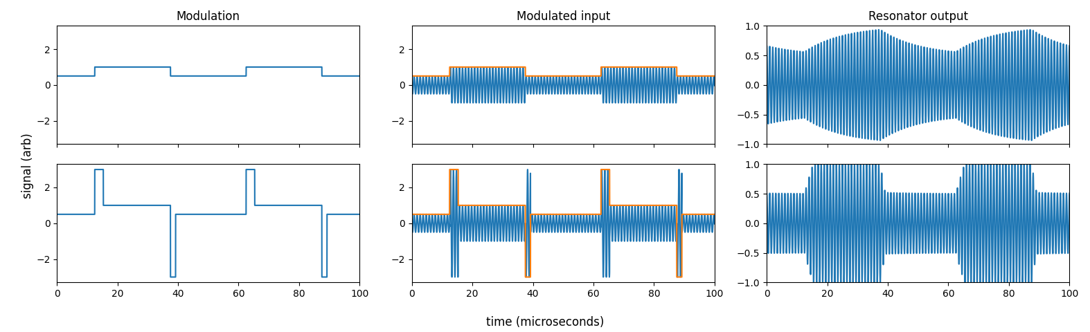
Here’s an example for a system with a Q of 40, a resonant frequency of 1 MHz, with $V_H$ = 1 V, $V_L$ = 0.5 V, and a $V_{max}$ = 3 V. The symbol rate here is 40 kHz, or put differently, a high- or low-amplitude state lasts 25 microseconds. In the top row (in which we simply modulate the input to the resonator with the desired output square wave), the resonator is nearly smoothing (filtering) out the modulation (rightmost plot). However, if we overdrive the resonator each time we switch states (bottom row, left and middle plots), as described above, then we get rapid, precise transitions between levels (bottom row, right-most plot).
And here’s the script that runs that analysis.
From a single resonator to two coupled resonators
All of the above analysis concerned a single resonator, not a pair of coupled resonances as in an inductive link. In the regime of very weak coupling, we could use the above scheme, plug in the drive coil Q, and ensures the drive coil has a step-like amplitude transition. But the voltage observed by the receiver still has to ring down on its own, so we’d still be stuck with the bandwidth limits of the receiver Q. Perhaps we can play the same trick for the overall system? Put differently, can we think of the whole system as having some equivalent Q?
For identical resonators in series, there’s an exact formula for the equivalent Q, published in 1973 no less! For the specific case of two identical resonators with some quality factor $Q$, the equivalent quality factor is about $1.554 Q$. If the Qs are unequal, for Qs in the range of 2-200, a good approximation for the resulting Q (measured as the resonant frequency over the -3dB bandwidth) is $Q_{equivalent} = \left( Q_1^{1.577} + Q_2^{1.577} \right)^{0.635}$.
Example 2
How well does this work? Here’s an example with the same parameters as example 1 above, except instead of a single resonator, it is two resonators in series with Qs of 40 and 20 ($Q_{equivalent} \approx 48$ for these combined resonators). This example is probably analogous to two weakly coupled inductors ($k \ll 1$), but may not hold for strongly coupled inductors.
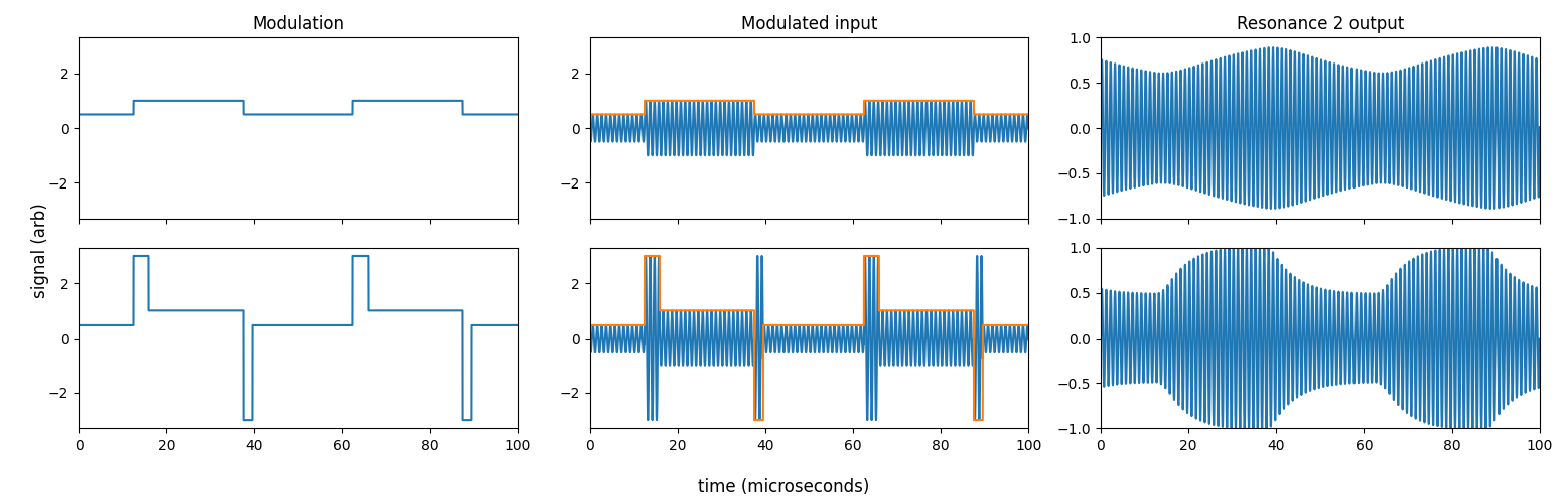
In this example, if we simply modulate the driving voltage (top row) you can clearly see that the 2nd resonator does not reach steady state when switched every 25 microseconds (in fact, its 10%-90% rise time is ~31 microseconds). However, if we overdrive the system (shown in the bottom row) as discussed above by using the effective Q of 48, the rise time improves ~3x, dropping to 10 microseconds.
What’s missing here?
- During this modulation, is power transfer efficiency still high? Or have we inadvertently sacrified power transfer efficiency when we have to overdrive the drive coil?